A sequencing batch reactor is a fill-and-draw type of conventional activated sludge treatment system. This approach was developed over a century ago and has proven to reliably treat municipal and industrial wastewater. More recent developments in wastewater treatment technology have made the SBR even more of an advantageous treatment method. With a variety of technologies available, it’s important to understand both attributes and challenges presented by the SBR to ensure the best possible outcome for a project.
Fill-and-draw batch processes have been applied in wastewater treatment since the early 1900s when Ardern, Lockett, and Fowler developed the activated sludge process in their laboratories in Manchester, U.K. (Ardern and Lockett 1914, Ardern and Lockett 2015). Since the development of the activated sludge process, continuous flow activated sludge plants dominated over fill-and-draw batch processes due to the lack of modern automation. In years past, manually adjusting valves, switching on and off pumps and the lack of level controls, etc., made the process onerous. Development of control systems and mechanical equipment in the 1960s, 1970s, and 1980s (Pasveer 1958, Irvine 1971, Wilderer and Schroeder 1986) laid the foundation for reviving the SBR process as a solution for municipal and industrial wastewater treatment. While the SBR process was quickly becoming more popular in small- and medium-sized plants, another approach to the SBR process was developed: the cyclic activated sludge process (Goronszy 1979, 1985, Demoulin and Goronszy 1997, Demoulin et. al 1999). It was developed and applied in larger wastewater treatment plants using the process names CASS (cyclic activated sludge system) and ICEAS (intermittent cycle extended aeration system). Similarly, more recently developed processes incorporate cyclic activated sludge reactors which are continuously fed with fresh wastewater while treated water is intermittently decanted from the reactor.
In more recent years was the development of a new SBR process, the aerobic granular sludge (AGS) process technology (de Bruin et. al 2004, Prout et. al 2015, Prout et. al 2017), which has received a lot of attention. An advantage of this process is the production of larger sludge granules than that of conventional activated sludge flocs. Larger flocs mean faster sludge settling. Larger floc size also allows for an anaerobic core, an anoxic mid layer and an aerobic outer layer in a single sludge granule compiling anaerobic, anoxic and aerobic driven process steps (e.g. P removal, denitrification, and nitrification) (see Figure 1).

If properly designed, AGS applications offer the potential for achieving:
- Higher MLSS without the use of plastic carriers
- Better settleability
- Reduced reactor volumes
- Smaller footprints
- Shorter cycle times
- Lower capital investments
- Higher process safety
- No need of internal recirculation pumps
- Less sludge production
- Decreased energy consumption
- Reduced operating costs
This is why more than a few commercial wastewater treatment system providers, other than the Dutch pioneer Royal Haskoning DMV, have attempted to develop, establish and market their own adaptations of the AGS. All current AGS advancements are based on the SBR principle of using one or more complete mixed reactors where the AGS is supposed to develop. This means to unleash the potential advantages of the AGS process, challenges which come along with the SBR concept, listed below, must be mastered.
- Precise hydraulic and load equalization of the flow is required and usually leads to large upstream mixing and equalization basins.
- It is necessary to overdesign the mechanical equipment because of limited runtime per process cycle and day.
- Accurately scaling up from lab‐scale and/or pilot scale to life-size and large-scale plants is challenging and requires in-depth understanding of fluid mechanics to be more reproducible.
- The prerequisite of obtaining completely mixed reactors can significantly limit the reactor, process, and equipment design.
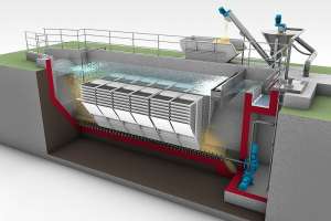
Controlled anaerobic feeding of raw wastewater into the settled sludge blanket is crucial for the kick‐off of granular sludge formation. To achieve this, the most common approach is to feed the reactor through a bottom feeder with flow throughout the bottom of the entire reactor and install a static decanter at the water surface as illustrated in Figure 2.
This approach works best in smaller circular or rectangular tanks with pipe works providing equal distribution of the raw wastewater throughout the bottom of reactor with the use of a static decanter at the top and when the required piping does not become too complex and expensive and does not result in too much of a hydraulic loss. The approach limits the volume per reactor module to smaller volumes and is the reason why these plants require large equalization basins upstream of the biological reactors, because an equal flow distribution at the bottom can only be achieved for the one exact hydraulic flow to the reactor for which the feed systems were designed. The slightest deviations from the designed influent flow will lead to nonuniform feed and distribution of raw wastewater in the sludge blanket, improper functioning of the static decanter and the operation of the plant as a whole. A further disadvantage of the bottom feeder system is the high hydraulic loss which is required to achieve equal flow distribution across the bottom of the reactor. Treatment dependence on precise flow makes treatment performance sensitive to minor flow fluctuations which can be caused by something as simple as sludge clogging the feeder piping.

Overdesigning may be necessary for different types of equipment. An example is the challenge in designing aeration systems for wastewater treatment for continuous flow processes. In this scenario, the aeration system is designed based on the daily oxygen demand, with hourly capacity calculated by dividing the daily value by 24. However, in systems with cyclic processes, like a typical SBR cycle lasting three or six hours, the aeration time per day is reduced to 16 hours or less. This necessitates a 1.5 times higher capacity for the aeration system compared to a continuous flow reactor. Consequently, more diffuser elements, blowers and installed power are required. Additionally, some SBR processes’ aeration phases overlap with the fill phases resulting in lowered aeration water depth in the reactor further reducing the overall aeration efficiency which the aeration system design must compensate for. Similar effects may apply to other equipment such as pumps and piping. This example highlights the potential for substantial improvements in process efficiency and the importance of a holistic approach to process, reactor and equipment design.
In laboratory-scale experiments, basic principles are often tested in small circular vessels, typically 100 or 200 mm in dimension, with volumes measured in liters. Equipment for mixing, aeration and pumping is sourced from laboratories or local aquarium shops. The transition from lab-scale to pilot-scale is the initial challenge, as larger-scale equipment is not readily available at the pilot stage. Consequently, pilot-scale setups often use large-scale equipment, leading to dissimilarities between lab and pilot scales. Moving from pilot-scale to large-scale, such as from 20 cubic meters to 1,500 cubic meters, presents additional challenges. Geometrical similarity is compromised due to limited availability of large-scale basins, and factors like floor coverage and piping must adhere to real-life constraints. The aeration system design faces challenges as well, with the air bubble diameter remaining constant despite scale changes, leading to unexpected mixing limitations in larger scales. This often results in suboptimal process performance, highlighting the importance of addressing mixing issues in large-scale applications. This is usually the moment when proper scale‐up stops because the step from large to larger scale can only be made by changing reactor footprint because otherwise the side water depth becomes unrealistically high.
The SBR process is based on a complete mix reactor behavior. To comply with this basic requirement, feeding and decanting becomes more and more demanding with scaling up to larger reactors. At times, this requirement is neglected and the process performance suffers for example. This is why some processes that work successfully at smaller scales sometimes face severe challenges in scaling up from large to larger scale.
To overcome these challenges an AGS processes and reactor design should incorporate the following four considerations.
- Continuous flow with intermittently decanted reactors has advantages because it has less water level fluctuations between low (end of decanting phase) and normal operating level. A more stable water depth helps to minimize hydraulic losses, reduce pumping energy requirements and optimize aeration system efficiency.
- Staged reactor designs are advantageous because they allow larger reactor volumes without making the common errors made during the up-scaling phase while offering a new special dimension of process design, especially if combined with a continuous flow approach.
- The overall design and operation should incorporate the ability to share mechanical equipment between each reactor to reduce additional equipment such as diffusers, blowers, pumps, etc., to avoid overdesign and reduce overall investment costs. An example is the use of blower stations that can switch between reactor modules.
- The whole system including key equipment should be flexible and be able to react to different flow and load scenarios to avoid the need for upstream mixing and equalization.
These considerations represent a condensed summary of collective experience gathered at the Department of Fluid Mechanics of the Friedrich‐Alexander University Erlangen‐ Nuernberg (Bischof et. al. 1991, Hoefken et. al. 1994, Manzolli 1994, Bischof et. al. 1995, Waechter et. al. 1996,) and at INVENT Umwelt‐ und Verfahrenstechnik AG (Hoefken 1995, Hoefken et. al. 1996, Hoefken et. al. 2003, Hoefken et. al. 2004) since the 1990s. The practical realization has been a long process with step-by-step improvements from project to project. Finally resulting in the INVENT iC3 Process which stands for cascaded reactor design, continuous operation, and cyclic process.
This process leverages the unique features of the HYPERCLASSIC Mixing and Aeration System (Hoefken et. al. 1991, Hoefken et. al. 1993, Hoefken 1994, Hoefken et. al. 2001, Hoefken et. al. 2004) which is ideally suited for intermittent processes. The INVENT SBR is characterized by the iC3 reactor module which is a drawn‐out rectangular basin with multiple HYPERCLASSIC Mixer/Aerators mounted in series to create individual complete mixed zones (cascaded). Wastewater continuously enters through a specially designed inflow distributor at one end and clear treated water intermittently leaves the reactor through operated decanting systems on the opposite end. This design makes it possible to develop and operate an optimized SBR cycle strategy which can vary from zone to zone.
INVENT differentiates five different process phases, which happen at different times and in four or more different spatial zones. These zones are defined by the four different spatial zones of equal size in which we can divide each SBR tank. In Figure 3 the five basic cycle phases of the INVENT SBR process are shown schematically.
- Fill/Mix (FM): Initial phase with slower mixing and no aeration, generating anaerobic conditions in zones 1 and 2 and anoxic conditions in zones 3 and 4.
- Fill/Mix/Aerate (FMA): High-speed mixing and aeration cycle, supplying oxygen for BOD and COD removal, nitrification, and maintaining aerobic conditions.
- Fill/Degas (FDg): Short period of strong mixing for effective degassing of sludge flocs, improving settling properties and preventing foam collection.
- Fill/Settle/Slow Mix 1 (FSPh1): Low-speed mixing during settling phase, promoting denitrification and anaerobic conditions for Bio-P release and rbCOD conversion.
- Fill/Decant/Slow Mix 2 (FDPh2): Continued low-speed mixing to create anaerobic conditions for Bio-P, decanting of treated effluent, and removal of excess sludge to maintain process efficiency.
After phase 5 the cycle repeats itself and jumps back to phase 1.