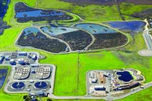
A leak in the 30-inch ductile iron pipe (DIP) feeding the headworks at the Punta Gorda (Florida) Wastewater Treatment Plant turned into a rehabilitation project for the city. The contractor patching the leak found he could put a finger through the deteriorated pipe.
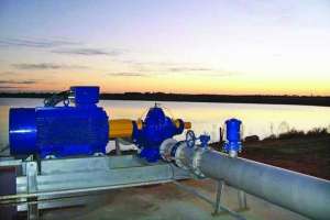
Thomas Traina, P.E., with King Engineering designed the upgrade and solicited help in design of a temporary bypass from the Tampa location of Sunbelt Rentals. “Our investigation determined the treatment system had less than 2 feet of head pressure,” says Eric Eaton, Sunbelt sales development manager. “However, the difference in elevation was sufficient to do a pipe-only bypass instead of relying on temporary pumps.”
It took almost a year to complete the bypass plan, which Michael Crowley, P.E., president of CAA Engineers, then stamped as required. “Mike normally just reviews all our large bypass calculations, but it was especially important because of this unique design,” says Eaton.
Before the bypass, scale and debris from the deteriorated pipe hindered flows and often reduced the plant’s efficiency. After the bypass went online in June 2014, operators noticed the plant ran better and was easier to control.
The 12 mgd (design) activated sludge plant treats an average of 4 mgd. Poole & Kent Company of Florida won the bid to replace the ductile iron piping from the connection to the 12-foot-high headworks to the four aeration basins, and from there to the four clarifiers. Asif Shaikh, Poole’s project manager, hired Sunbelt to install the bypass.
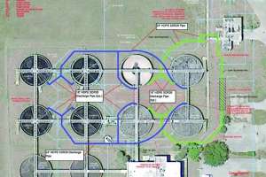
“We worked closely with Asif to coordinate our efforts and complete the project during Florida’s dry season,” says Eaton. “Even before the start date, we were fusing 50-foot sticks of 18- and 24-inch HDPE SDR 26 pipe (Performance Pipe) at the plant.” The longest run was 250 feet of 24-inch pipe from the headworks to the west aeration basins. The 18-inch discharge lines to the tanks were 10 to 15 feet and 20 to 25 feet long.
The headworks connection was a 30-inch underground tee to which Poole installed a universal MEGALUG mechanical joint followed by a short length
of 30-inch DIP and an adapter ring for a 150-pound flange (weight designated a 20-bolt pattern). When Eaton received permission to move in, his four-member team mounted a 30-inch to 24-inch reducer on the flange and connected the temporary 24-inch line.
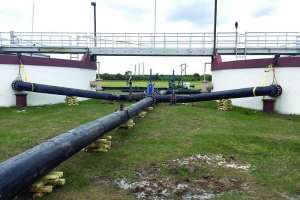
The Sunbelt crew used two 8,000-pound-capacity forklifts and one 6,000-pound-capacity forklift to position the pipe sections in the fusion machine and move the fused lengths around the site. “Even pipes this large have a little friction loss through bends and tees,” says Eaton. “Therefore, it was critical that the runs lie flat with minimum direction change to avoid any further friction loss.”
Each pipe had an HDPE saddle to compensate for contraction during temperature and pressure changes. The clamps had a threaded connection and an O-ring. “We drilled through the connection, then used the hole to install vents or use as a port to inject water,” says Eaton.
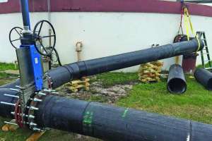
His crew installed 18-inch knife gate valves (all identical valves from Orbinox) with 16 bolts per flange where the 24-inch pipes transitioned to the smaller discharge lines. “That enabled operators to take aeration basins or clarifiers out of service during low flows and send it all to one side,” says Eaton. They also closed the valves and pressure-tested the 24-inch system to 20 psi. The joints were perfect.
Poole’s team needed access to the area between the east and west clarifiers to build a concrete distribution box. To ensure an unobstructed path, Eaton’s team excavated a 3-foot-deep trench in front of the aeration basins and buried the section of 24-inch pipe running in front of them. Steel road ramps placed over the trench allowed heavy equipment to cross it. “We also routed the bypass around the outside of the tanks to keep the center aisle open,” says Eaton.
Once the pipes were laid out and during low-flow conditions, operators closed the feed lines to the tanks and drained them as needed. While Poole removed the existing tees 6 feet above grade for the tank’s feed line and air vent, Eaton’s crew added a 24-inch tee from the main bypass line to between two basins. They inserted a 24-inch to 18-inch reducer and valve at the ends of the tee, and connected them to short lengths of 18-inch pipe extending to the tanks.
“We vented our system to mimic the original piping,” says Eaton. “Because we had isolating valves, we turned on the bypass as each tank was hooked up.” To help equalize the system during elevated flows, workers fused an 18-inch crossover pipe with valves and left it behind clarifiers 2 and 4 for Poole to hook up if needed. The bypass took three weeks to install.
Poole completed the project months ahead of schedule. Eaton’s team decommissioned the bypass in less than three days. They flushed the pipes with effluent, drained the system, then attached a pump to the saddle on the short length of 30-inch DIP on the underground tee, and pumped out any residual water.
“We unbolted the flanges where possible, or sawed them out with a chain saw and removed the bolts at the shop,” says Eaton. “The pipe was sawed into 50-foot lengths and hauled home to use again.”