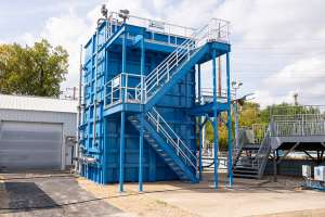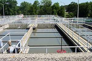
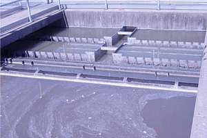
When the Village of New Lenox, Ill., wastewater treatment facility recently faced a plant expansion, operators quickly realized that it was not as simple as expected. Adding three primary clarifiers at the main activated sludge treatment plant increased capacity from 0.75 to 1.5 mgd.
Before adding the clarifiers, all flow went directly to the aeration system. The clarifiers reduced solids loading by 60 percent and BOD loading by 30 percent so the facility can handle more influent with the same number of aeration tanks. They’ve also increased influent flow by 30 percent.
However, when the clarifiers became operational operators immediately knew there were a few problems. See how this plant’s ingenuity paid off and what your plant could do if faced with similar obstacles.
Initial setbacks
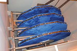
With shared center walls and influent and effluent channels, the rectangular clarifiers must perform cohesively to operate properly. When they were brought online and water started to flow, the first clarifier had almost no water flowing over its weir and the third clarifier had twice as much water flowing over the weir as clarifier number two.
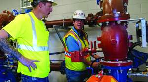
The way the water entered the influent channel was causing the problem. The influent came in from the bottom but then had to pass through a 90-degree elbow, turning it toward the channel. The elbow was followed by a shut-off valve, and the valve discharge was right next to the influent gate for the first clarifier. The flow velocity being pumped into the channel was causing the water to bypass primary one and partially bypass primary two.
Operators removed the 90-degree elbow and the shut-off valve so the water would come up from the bottom of the channel and distribute the flow more evenly. There was a better distribution of flow between the three channels, but clarifier one still had the lowest flow and clarifier two still had less flow than clarifier three.
Adjusting the effluent weirs in each primary to equalize the flow was the solution. The weirs were initially all set at the same level, so operators lowered the second clarifier’s weir down 1/4 inch and the first clarifier’s weir down 1/2 inch. Setting the three weirs to different levels evened out the flow. The sludge blanket buildup is now about the same in each clarifier and operators pump about the same amount of sludge out of each clarifier every day.
Next up!
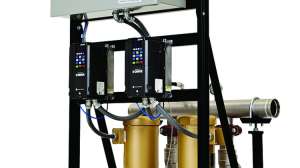
The next setback involved the two hoppers on each clarifier. Each hopper had an effluent line for sludge to be drawn off to the sludge pumps. The two discharge pipes from each clarifier went to a common header. An automatic valve on each clarifier on a timer system pumped effluent to biosolids handling. With both valves on each clarifier open to the hoppers, sludge only came from the hopper with the lightest solids concentration. Thicker sludge from the other hopper did not flow to the sludge pump.
With only one hopper working properly, rising sludge in the primary clarifiers was an issue. The plugged hopper would turn septic and sludge would rise up no mater how low operators kept the sludge blanket in the clarifier. To solve this problem operators closed the valve from one hopper for a day and only drew off the other hopper. Then they alternated the next day, closing the valve that was open the previous day.
Today, operators rotate hoppers more frequently than once a day or the isolated hopper can plug. This easy and inexpensive fix means operators can now maintain a blanket without plugging the effluent lines.
Grease accumulation
The influent channel to the primary clarifiers also had a problem with grease accumulation. The influent gates to each clarifier that allow water to enter the primaries are below the water level in the channel and the clarifier water level. As a result, grease floating in the influent channel cannot flow into the primary clarifiers and tends to accumulate in the influent channel.
The grease either had to be manually removed with buckets or one clarifier would have to be taken offline and drained down below the influent gate level. Operators then had to open the gate and allow the channel to flow into the partially drained clarifier, allowing the grease in the channel to flush into the partially drained clarifier. Both options were time consuming and difficult to do on a routine basis. And because the plant is located in downtown New Lenox, odor is a major concern and during summer months the floating grease buildup in the influent channel added to odor problems.
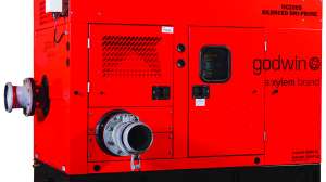
Operators decided against installing new gates and modifying the influent section so the flow could enter the tank at the water level because it was too expensive. Investing in a positive displacement pump, which would pump the grease off the influent channel, was also cost prohibitive.
Covering the influent channel and deodorizing the air removed from the channel to prevent odor was less expensive; however, grease would still be a problem. They needed to get the grease to gravity flow into the clarifier by some other means.
Levelheaded solution
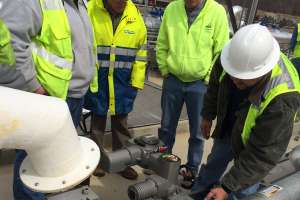
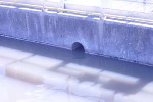
Operators cored a hole between the influent channel and the clarifier so the grease would work its way to the end of the channel and floats out into the clarifier. The 8-inch hole goes through the wall with the center of the hole at the water line. The grease flowed to the end of the channel and into the last final clarifier. Operators didn't need to hose the grease and force it into the last primary.
The flow didn’t change in the clarifier with the cored hole. Based on the tanks’ sludge blanket and the draw off rate today, operators know the effluent weir level that regulates the flow to the three clarifiers and the hole at the water level did not affect the total flow as a result of the modification.
One problem solved, another created
Of course with one problem solved, another was created. As a result of the coring modification operators had to deal with keeping flow from going into the clarifier when it was shut down for service. Even when they closed the inlet gate, the cored hole would allow flow to enter the clarifier.
Some of the suggested solutions included:
- Put a pipe through the wall and cap it to stop flow to the clarifier.
- Put some type of valve on one side of the hole that could be closed to drain the clarifier.
- Put an inflatable rubber plug in the hole when the clarifier was shut down.
The inflatable rubber plug turned out to be the best and least expensive solution.
Utilizing the team of experienced operators worked out well for the New Lenox plant. By working together to fix the issues related to the primary clarifiers, operators have more control over operations. They have a sense of pride knowing they helped ensure the facility is operating efficiently and cost-effectively.
For a complete profile on the New Lenox plant, visit www.tpomag.com/editorial/2011/04/forward_thinking.
About the Author
Mike Turley is supervisor of Waste Water Reclamation for the Village of New Lenox, Ill., overseeing three treatment plants with a combined 3.6 mgd flow.