The word cavitation comes from the Latin word “cavus” meaning hole or cavity. Cavitation refers to conditions within the pump, when the local pressure drops below the vapor pressure of the liquid, and cavities filled with water vapor form. The cavities collapse as soon as the vapor bubbles reach regions of higher pressure.
Cavitation is one of the most important causes that affect performance, operability, reliability and pump life.
A general local pressure drop may be produced by one of the following:
- An increase in the static lift of the centrifugal pump.
- A decrease in the atmospheric pressure with a rise in the altitude.
- A decrease in the absolute pressure on the system.
- An increase in the temperature of the pumping liquid, which has the same effect as a decrease in the absolute pressure of the system.
- An increase in the velocity fluid, increasing the velocity of the pump.
- Deviation of the streamlines due to obstruction or turn (swirl) by the geometry design.
- Sudden starting and stopping recoil of the water column may also cause low absolute pressures and cavitation.
Calculating NPSHR and NPSHA are important and will help avoid cavitation.
NPSHR is the net positive suction head required by the pump to avoid cavitation. General guidelines define NPSH as a 3 percent drop in total dynamic head (TDH) of the pump.
The pump manufacturer determines this value and it is generally measured by reducing the suction pressure until the pump head has decreased 3 percent compared to the condition without any cavitation. This method is explained in depth by the Hydraulic Institute. (Figure 1)
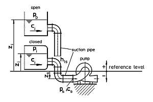
NPSHA is the net positive suction head available of the system to the pump, and it is calculated during design and construction or determined from the actual system. And a valid equation to determine the NPSHA is:
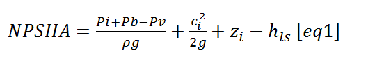
Where:
Pb = atmospheric pressure (barometric pressure)
Pv = vapor pressure of the delivery fluid
Pi = pressure in the closed intake vessel
Ps = pressure at the suction branch
ρ = density of the delivery fluid
ci = velocity of the fluid in the intake vessel
cs = velocity of the flow at suction branch with the data at the pump included
zi = elevation of the liquid level in the intake vessel to the pump axis
zs = elevation of the suction branch to the pump axis with the data at the pump included
Various causes create different types of cavitation. Some of them include:
General cavitation is the most common type and it is caused by insufficient NPSHA. It occurs when the NPSHR value is larger than the NPSHA value. So it is created by a reduction of Pb, Pi, zi or increase of Pv. Therefore the NPSHA needs to be at least equal to the NPSHR or a much greater margin than NPSHR. In Table 9.6.1.1, the Hydraulic Institute recommends a certain NPSH margin ratio (NPSHA/NPSHR); the recommendations are based on the field experience of many pump manufacturers with different pump applications.
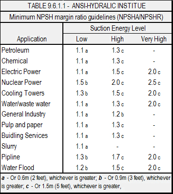
Nevertheless, the best ratio of NPSHA/NPSHR causes the least amount of damage to the pump.
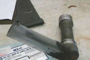
Damage signs of general cavitation are on the low-pressure area of the vane. It is always characterized as being rough, sometimes jagged with striations running in any direction.
The most common solutions to avoid general cavitation:
- Increased zs, zi
- Reduce the operating temperature of the fluid, which will decrease the vapor pressure (Pv) and increase the NPSHA
- Sharpening the leading edges of the impeller vanes at the pressure side to increase the eye area between vanes
- Pump life can be extended, but cavitation exists if select material is resistant to the cavitation
Inlet cavitation occurs at the inlet diffuser of the pump, impeller eye and near the suction.
Inlet cavitation happens when a low flow rate induces the reverse of the fluid at the suction inlet, and turbulence in the piping creates a vortex large enough to allow change in the direction of the fluid, creating changes in the local pressure reaching the vapor pressure of the fluid.
The high velocities created by the vortex results in cavitation. Such cavitation has a distinctive intermittent noise like crackling, hammering or knocking. This sound is different from other types of cavitation and can be a first diagnosis of the cavitation problems.
As inlet cavitation is a result of the velocities of the fluid, the worst operating condition is on the high capacity side of the H-Q, performance curve.
Another diagnosis is the damage at the pressure side of the vanes there we could find pitting on the leading edge of the vane.
Recommendations to avoid inlet cavitation:
- Lower rotating speeds are less sensitive to intake problems
- Work in the allowable operating region as defined by ANSI/HI
- Avoid large changes in the diameter of suction inlet piping and pipe turns that can cause vortex
- Use splitters to reduce vortex
Exit cavitation occurs due to reverse fluid at low flow rates. It happens at the discharge side of the impeller and near of the discharge nozzle.
Low-speed pumps are less sensitive to exit cavitation but increasing the speed increases the chance to damage. At high speeds wider spacing vanes generate more area susceptible to vortex.
Similar to inlet cavitation, the noise associated with exit cavitation is distinctive and heard at the discharge side of the pump.
Pitting and damage can be seen in the trailing edge of the vane, discharge side of the impeller and around shrouds of the impeller.
Recommendations to avoid exit cavitation:
- Work inside the allowable operating region
- Run pumps at lower velocities
- In the cases that open impellers present pattern damage, round the corners of the vanes at trailing edge
Incipient cavitation represents the beginning stage of cavitation when the bubbles are small. It is present in almost all pumps most of the time.
Incipient cavitation is the 3 percent head drop, or the threshold formation of vapor phase bubbles. Normally there is no mechanical damage but some corrosion may start.
Incipient cavitation is present mostly in high-energy pumps, those with high suction specific speeds (Nss>9500), and pumps with higher NPSHA/NPSHR margins.
The NPSHA/NPSHR margin ratio indicates low suction specific speeds and low-energy pumps, and the 3 percent pressure reduction represents a small amount of cavitation. For pumps with high suction specific speeds and high-energy pumps, the 3 percent pressure reduction represents much more cavitation.
So, the 3 percent drop it total dynamic head is relative to the kind of pump being analyzed.
Some of the general diagnosis of cavitation can be:
H-Q and efficiency drop
The degree of the drop in H-Q and efficiency curves depends on the specific speed and suction pressure. With higher specific speed pumps (Nss>6000), the H-Q curve drops gradually along the entire curve, while with low specific speed pumps the drop is sudden.
This is caused by the impeller design. In low specific speed pumps the impeller vanes form a complete channel that reach the vapor pressure faster, on the high specific speed pumps the space between vanes is wider and shorter, therefore more head drop and capacity are needed to extend the vapor pressure along the entire impeller channels.
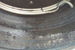
Pitting, corrosion and abrasion
Cavitation also causes corrosion, pitting and abrasion. Prolonged exposure to cavitation can form pitting in different parts of the pump. Corrosion and abrasion can also occur on materials that are resistant. This happens because the surface oxidation film that forms on some materials, like stainless steel, is removed by the explosion of the vapor bubbles and corrosion is accelerated.
The following materials offer good performance between cavitation and corrosion where cast iron is the least resistant and stellite is the most resistant:
- Cast iron
- Bronze
- Cast steel
- Manganese bronze
- Monel
- Cast iron, CA-15, CA6-NM, CF-8M
- 400 series stainless steel
- 300 series stainless steel
- Duplex
- Nickel-aluminum bronze
- Titanium
- Stellite
Other factors, such as heavier liquids can increase cavitation. Impeller and casing design can cause changes in direction or acceleration of the fluid increasing the cavitation.
Small amounts of entrained gas (1 to 2 percent) can cushion the forces and reduce damage but any lack of the gas has the opposite effect and could block the inlet area of the flow and increase cavitation. The corrosive properties of the liquid also can accelerate the damage.
The following recommendations can decrease cavitation:
- Good knowledge of the application and cavitation characteristics
- A careful analysis of the suction conditions and selection of the pump
- Knowledge about fluid pumping
- Study of the pump design data, H-Q curves, NPSH curves
- Increasing the NPSHA and avoiding too much margin
- Increase of the suction size and reduction of the pipe length, avoiding sudden turns
- Increase the number of vanes in high suction specific pumps
- Opening the inlet area of the flow in low specific speed pumps, sharpening the leading edge
- Redesign impeller
- Using a more cavitation-resistant material
Cavitation is much more complex than it seems, but new technologies such as CFD (Computational Fluid Analysis), and experimental tools have been developed to predict and avoid cavitation. Manufacturers are studying these new tools to provide reliable solutions for the prevention of cavitation in pump applications.
About Ruhrpumpen
Ruhrpumpen is a centrifugal pump manufacturer that offers process pumps, fire pump packages, decoking systems for the markets in oil & gas, petrochemical, power, heavy industry applications, mining and water, complying with API, ANSI, Hydraulic Institute, UL, FM and ISO 9001. For more information, visit www.ruhrpumpen.com.