Interested in Treatment?
Get Treatment articles, news and videos right in your inbox! Sign up now.
Treatment + Get Alerts
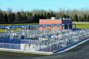
Heavy rains flowing through the Ohio city of Springfield’s combined sewer system overwhelmed the wastewater treatment plant. The city averaged 50 to 70 CSOs per year, discharging up to 90 mgd to the Mad River.
In 2012, the city agreed with the Ohio EPA to build a 100 mgd high-rate treatment wet weather clarifier and to have the agreement added to its NPDES permit. The agency gave the city a July 2015 deadline.
The review committee evaluated bids and selected the WWETCO FlexFilter compressible media filtration system from WesTech Engineering. “The technology was brand new,” says Bill Young, acting plant superintendent. “Only one small unit was treating stream water in Georgia. Our application was totally different and would be constructed on a massive scale.”
To gather vital information for the design engineers, operators ran a 400 gpm demonstration unit from September 2010 to November 2011. Their tests confirmed criteria for specifying 11 filtration cells including loading parameters, media size and operating conditions. The clarifier entered service in January 2015. Today, it treats excess flows with effluent averaging 19 mg/L TSS and 24 mg/L BOD.
How it works
The clarifier traps pollutants in cells 30 feet long, 22 feet wide and 12 feet deep, each designed to filter 10 mgd. As influent trickles down through 30 inches of synthetic fiber balls, hydraulic pressure flexes a bladder (reinforced rubber sidewalls) inward, compressing the media from the bottom (highest compression) to the top (no compression). This pressure gradient captures a high volume of solids by trapping large particles in the top portion and fine particles farther down.
The process uses no mechanical actuators or other moving parts, relying solely on incoming hydraulic forces. Once the water overflows into the media, the filtration process begins. There is no ramp-up period after bringing the system online. It treats the flow passively.
Rising influent levels activate the cleaning cycle. Draining the cell flexes the bladder outward, releasing the compressed bed. After an air-scoured backwash cleans the media, the filtration cycle repeats. Effluent passes through a chlorine contact basin and discharges to the river.
Besides the 310- by 100-foot clarifier, the $52 million upgrade included a wet weather headworks with four 40 mgd horizontal raked bar screens (Process Wastewater Technologies), a rock box, gate valves, 20 hp lobe blowers (Roots Systems), sodium hypochlorite and sodium bisulfite feed pumps (Watson-Marlow Fluid Technology Group), and 310 hp effluent pumps (Flygt, a Xylem brand). An Allen-Bradley programmable logic controller (Rockwell Automation) with touch screen enables operators to make adjustments easily.
Upgrades to the 40 mgd (design) complete-mix activated sludge plant included two RakeMax multi-rake influent bar screens and three shaftless screening conveyors (Huber Technology), an anaerobic digester, a 140-foot-diameter spiral blade secondary clarifier, and rehabilitation of two 2.2-meter Tower Press belt filter presses (Charter Machine Co.).
Pride of ownership
Seven operators (only one per shift) manage the plant’s daily average flow of 15 to 17 mgd. They all contributed to the upgrade’s design, and it paid dividends. Engineers had the filter backwash water discharging to the three flight screw pump basins at the headworks. This reduced the plant’s capacity to treat wastewater. To restore it, operators suggested directing the backwash to the influent channel of the complete-mix activated sludge basin.
“That was a major change,” says Young. “The team also relocated some chemical lines to the chlorine basin and made it more efficient.”
When the demonstration unit arrived, WesTech representatives trained operators to use the PLC, a TSS meter and variable frequency drives to control flow rates. However, no one had tested the unit in cold weather. “I wanted to see how it operated as a solid block of ice,” says Young. With temperatures in the mid-teens, an operator filled the system with water, ran it for 20 minutes, shut it off, and drained it. The mercury dropped below zero that night and stood at 10 degrees F the next morning. When the pumps were turned on, warm effluent from the plant thawed the media immediately, and the unit functioned flawlessly.
Startup
In January 2015, the SCADA system brought the clarifier online seamlessly. “When the 84-inch sewer backs up for 6 feet, SCADA dumps the excess flow to the wet weather influent line,” says Young. “At 5.7 feet, SCADA switches the clarifier to standby mode, which activates the first four cells. If the flowmeter says more cells are needed, they open automatically.”
Last year, the plant activated the system 20 to 30 times and used up to seven cells. The design calls for nine active cells and two in backwash. During the first months, a major rainstorm caused the clarifier to hiccup. It closed valves at the wrong time, sending combined flows out the top of the cells and onto the contained service road. In response, the operator switched from the automatic mode to manual on the PLC touch screen, then opened the inlet valves to empty cells and catch the overflow.
“The stormwater carried a high amount of TSS that filled the filters in the first four cells and activated the backwash cycle,” says Young. “However, the PLC failed to open valves to new cells before closing other valves for backwashing. We traced the problem to setpoints in the PLC programming and changed them.”
Optimizing the outcome
Then operators discovered that frigid air settled in the empty cells, turning them into giant freezers. During monthly midwinter thaws with days above 32 degrees and nights below freezing, conditions in the cells formed ice around the gate valves, causing startup problems.
Thaws also brought heavy rain. “When rain was in the forecast, and to ensure the valves worked, we manually sent effluent from the secondary clarifiers to the first four cells,” says Young.
“That provided enough heat to melt the ice.” Operators worked with the engineer to program the deicing mode into the SCADA software.
Basically, the wet weather system runs itself, but operators occasionally still find little things to fix. One situation that went unnoticed was sodium bisulfite flowing back from the dechlorination/post-aeration basin to the chlorine contact basin. That caused the sample pump to give false chlorine residual readings and operators to feed additional chlorine.
In time, they became suspicious and began grabbing hand samples. More realistic numbers revealed the problem. Following the suggestion of Class 3 operator Kirk Morris, workers installed baffles in the bottom of the contact tank to help stop the backflow.
“The system is easy to monitor, dependable, and doesn’t require a full-time operator,” says Young. “We met our compliance deadline and ended CSOs. Now we’re looking at phosphorus removal.”
After Young fed alum to the plant effluent and sent it to the FlexFilter to verify it was able to catch floc, he designed a preliminary 12-month study. It will determine which is more economical: catching floc in the main plant or in the wet weather clarifier.