If you’re faced with running a sophisticated treatment plant, it helps if you have your operators involved in the design. That was the approach in Meriden, Conn., and it’s paying off in staff morale, operating efficiencies, and effluent quality.
The 11.6 mgd (design) Meriden Water Pollution Control Facility uses a unique two-stage activated sludge process that provides a number of treatment options, including nitrification, denitrification, and chemical and biological phosphorus removal. It’s supported by a 2,100-data-point SCADA system, complex enough to give most operators at least an occasional headache.
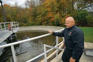
“We made sure our operators and maintenance people sat down with our management team (director of Public Utilities Dave Lohman and superintendent of Water and Wastewater Operations Dennis Waz) and the engineers as the plant was being designed,” says Frank Russo, plant manager and chief operator. “Things sometimes look good on paper, but plant people can make suggestions that result in easier maintenance and less cost when things are running.”
In addition, Russo explains, the SCADA system programmers came to the plant to work side by side with his staff so that both groups could fully understand and contribute to the automation protocol of each phase as it was installed.
While the upgraded Meriden treatment facility started up just over a year ago, it occupies a very old site. Parts of the collection system date back to the late 1800s, and a trickling filter went into operation in the 1960s. That was replaced with advanced secondary treatment around 1980. The new design, provided by AECOM, upgraded almost everything.
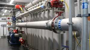
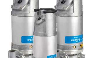
To begin with, there are two influent channels. Some 80 percent of the flow comes into the plant through a pumping station equipped with four 8,000 gpm Fairbanks Morse pumps with variable-frequency drives. The rest, from another portion of the collection system flows by gravity and enters directly through a separate sewer line into the headworks building. The configuration is more economical than adding more pump station capacity, says Russo.
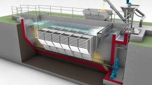
In the preliminary treatment stage, new Huber RakeMax screens and a chain and screw-type grit removal process prepare the wastewater for primary treatment. Three primary clarifiers follow the grit chamber, and a splitter box controls the flow among them. Each clarifier is 85 feet in diameter with a 10-foot side water depth.
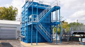
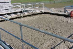
Primary effluent is routed to the first activated sludge treatment stage, consisting of four basins. The first-stage mixed liquor is then settled in four first-stage clarifiers before flowing to the second-stage activated sludge process, consisting of three aeration basins and a separate set of clarifiers.
For disinfection, Meriden uses chlorination-dechlorination with sodium hypochlorite and sodium bisulfite. From there, the effluent flows down a cascade re-aeration system into the Quinnipiac River and eventually to Long Island Sound.
Waste activated sludge from both stages is thickened on a Komline-Sanderson gravity belt thickener, mixed with primary sludge, and then dewatered on one of three tower belt filter presses supplied by Charter Machine Co. Depending on the blend of raw primary and thickened waste activated sludge, the resulting biosolids cake averages 20 to 26 percent solids. A tractor-trailer hauls it to an incinerator operated by Synagro.
The two-stage activated sludge system is unusual, both in how it is configured and in how Russo and his team operate it. Both systems are designed with the flexibility to run the basins in parallel or series, although typically they operate in a series, or plug-flow mode. The first-stage tanks (each 56 feet wide, 100 feet long, and 18 feet deep) are segmented into anerobic-anoxic-oxic zones with flexible internal mixed liquor recycle routing to achieve biological BOD, total nitrogen and total phosphorus removal.
The first stage removes about 60 percent of the nitrogen and also removes phosphorus biologically. The second stage provides anoxic denitrification polishing, using methanol, and includes a re-aeration zone in the final half of the last basin. Each stage has its own set of 105-foot-diameter, 14-foot-deep SWD clarifiers and its own return and wasting system.
“When they moved to advanced secondary treatment in the 1980s, the plant was designed and built as a two-stage system,” says Russo. “One stage was designed to remove ammonia and the second stage to remove BOD. They were operating the two trains as a single system, followed by clarification.” Now, the two-stage system provides much-needed flexibility. Russo explains that the first stage can be run in any of three modes:
• Completely aerobic for BOD and ammonia removal
• As a Modified Ludzack-Ettinger (MLE) process for BOD and partial nitrogen removal
• As an anaerobic-anoxic-oxic system (similar to the A2O process) for BOD, nitrogen, and phosphorus removal.
The second stage typically serves as a nitrate polishing step but can also be configured for BOD and ammonia removal and can run in parallel with the first stage if additional aerobic treatment capacity is needed.
“With phosphorus limits coming down from the state in the near future, I expect we’ll operate the first stage as an anaerobic-anoxic-oxic system in the summer to meet the seasonal requirements of our anticipated phosphorus limits,” says Russo. “In winter we’ll run it in the MLE mode.”
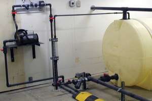
The plant also includes a backup chemical system using iron salt addition for phosphorus removal upstream of both the primary and second-stage clarifiers. In addition, the plant has capability for dosing ferric chloride into the belt filter press feed lines to aid in coagulation, assist with odor control, and drop out excess phosphorus from the filtrate before it drains back to the plant headworks.
The two stages also give Meriden additional flow routing flexibility to handle wet-weather flows. That’s an issue with the community’s aging sewer system, although 35,000 feet of sewer line were recently relined, and 1,600 vertical feet of manholes were repaired and sealed against inflow and infiltration.
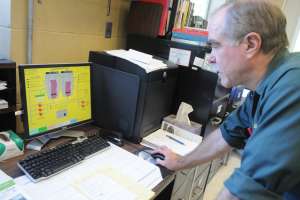
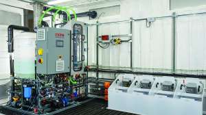
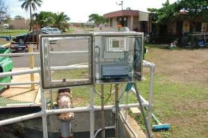
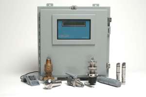
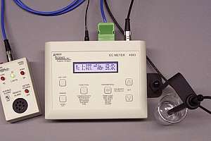
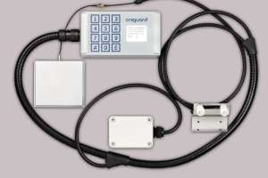
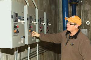
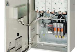
This kind of flexibility brings a level of complexity, and that is why Meriden has placed so much value on its SCADA installation. It’s a Honeywell Experion system, programmed and implemented by the control systems group of Siemens. “Our system monitors and controls some 2,100 points around the plant and in the pump stations,” says Russo. “It helps us to monitor, control and fine-tune the system on a daily basis.”
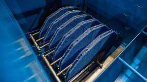
The instrumentation includes a pair of Hach LDO probes in each of the seven aeration basins, as well as a number of other analyzers, by Hach and Endress+Hauser. These are located throughout the liquid train for ammonia, nitrate, TSS, ORP, PO4 and pH. All the analyzers are tied back into the SCADA system, making it possible to review recent and historical trending data.
“All our aeration basins are controlled by our DO meters,” Russo explains. “This enables us to control DO in each individual basin. We can control both sides or halves of each basin and finely tune the system for optimum nitrogen and phosphorus removal.
“We use ORP to control the anaerobic environment in the first stage, and we control methanol dosing in the second stage based on our ORP values. Part of our flexibility is that we also have the ability to control methanol dosing from either the influent or effluent nitrate analyzers in the second stage via a PID loop. We know when we’re achieving maximum nitrate or phosphorus removal.” The values reported by the various analyzers can also be used to control chlorine dosage.
Meriden generally runs the first set of aeration basins with a mixed liquor suspended solids (MLSS) of around 3,500 to 4,000 mg/l. In the second series of aeration basins, a thinner MLSS level is maintained — around 1,500 to 1,800 mg/l. “In the second stage, all the bugs have to do is consume methanol and reduce nitrate,” says Russo. “So we don’t have to waste as much. Our solids retention time can be as much as 50 days, whereas we generally run at 17 days retention time in our first stage.”
The new system has been working very well. “We’ve had the denitrification systems online for over a year now, and we’ve seen effluent total nitrogen below 1 mg/l during the summer and low-flow periods,” says Russo. In recent months, effluent BOD has been around 3 mg/l, and suspended solids have ranged from non-detect to 4 mg/l.
After the biological phosphorus removal system had been online for about four months, Russo and his staff were still fine-tuning it. “During the past summer, we recorded total phosphorus between 0.3 and 0.6 mg/l, with a few days as low as 0.26 mg/l,” Russo says.
Meriden’s SCADA system also controls the truck loading rates in the biosolids building, an arrangement Russo says works very well. “ Our hauler lets us know how much weight a given trailer can hold,” he reports. “We then enter that number into our SCADA system, and when the scale the trailer sits on reaches our target weight, the system sounds an alarm and automatically initiates a controlled shutdown of our belt filter presses.
“We get maximum loads — about two trailer loads a day, four days a week — helping to control our solids-handling budget, and our hauler never has to worry about overweight loads.”
Russo attributes much of the new system’s success to education and the involvement of the operations and maintenance staffs in the design of the plant and in the implementation of new technology. “One of the most valuable lessons we’ve learned is to listen to your operators and maintenance people in the field,” Russo says. “I can’t be everywhere, but our operators are everywhere. They could see things as we went along with the upgrade, and they could question what we’re doing and maybe suggest a better way.”
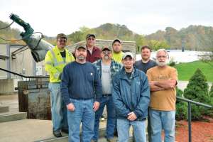
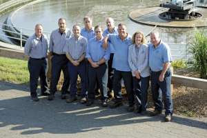
Besides Russo, Waz and Lohman, the plant team includes assistant manager Mike Cerreta; maintenance foreman Rene Laliberte; chemist Carmen Krzesik; lab technician Mike Komarenko; electronics technician Jon Yoder; maintenance mechanic Peter Villa; operator II Peter Stone; operators I Dale Paul, Jay Nedza, Walter Liss, Steve Estrom, Steve Belote and Todd Wollenberg; and administrative secretary Debra Hazen.
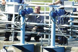
Russo offers an example of staff ingenuity involving the positioning of the two new JWC Muffin Monster grinders in the screenings building. “The original layout looked good on paper, but our operators suggested we install the machines in opposite directions to each other so that they would have better access to the units for maintenance,” says Russo. “We don’t have to unbolt the machines from the floor. Their suggestion has saved us many, many hours in maintenance time.”
Likewise, the plant staff was closely involved with the SCADA system installation. “We put small parts of the system online, one at a time,” Russo says. “Once our operators got used to each part, we moved on to the next and trained them further.”
Russo says the programmers came in for as long as a week at a time, providing training in the SCADA system for all the operators. Then they followed up with one-on-one training. It’s still a learning process, but the sequential approach has been extremely helpful. “We get information from everybody,” he says. “It really helps us make our plant operator-friendly.”